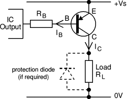

We will talk about how this voltage inversion could be designed to ensure that the operating point correctly switches from cut off to saturation along the load line as shown in the following figure:įor the present scenario, in the above figure we have assumed that IC = ICEO = 0 mA, when IB = 0 uA (a great approximation with regards to enhancing construction strategies).

The collector has a DC source which corresponds to the supply levels of the system, for example 5 V and 0 V in this computer application case.

Here you can find that the output voltage Vc is opposite to the potential applied across the base/emitter of the transistor.Īlso, the base is not connected with any fixed DC source, unlike amplifier based circuits.


 0 kommentar(er)
